Laser Marking and Machine Vision
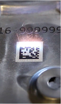
Laser marking is widely used across many industries that have high volume production lines, such as aerospace, automotive, medical, and electronics. This method of marking can be used across a range of materials, metals or plastics, making it a leading solution for production part marking. However, marking is only one part of the process of package identification; the mark often needs to be read, verified or inspected automatically.
This is where lighting becomes critical. Laser marking can be applied to a wide range of materials and surfaces, but this variability can make automated inspection challenging. The right machine vision lighting helps control reflections, improve contrast and create a more homogeneous image, allowing the marked code to be read reliably.
Why are Laser-Marked Codes Difficult to Inspect?
Although laser marking can produce highly precise codes, achieving consistent machine vision inspection is not always straightforward. Several factors can influence how clearly a code appears to the camera.
Materials
Laser engraved codes are commonly applied to metals, plastics, and coated surfaces, each of which interact with light differently. Reflective materials like polished metals can direct light back towards the camera, creating bright spots or glare the obscure parts of the code. Other materials may absorb light or produce insufficient contrast between the marked area and the surrounding surface.
Surface Finish
Polished surfaces can produce strong specular reflections, whereas brushed or textured finishes may scatter light unevenly. Coatings and surface treatments can also alter the contrast between the code and the surrounding material. Therefore, one lighting setup can work well on one finish but might perform differently on another.
Part Shapes
A component’s shape can affect how evenly the code is illuminated. Curved, angled or irregular surfaces may cause light to fall unevenly across the marking area. Changes in surface orientation can also introduce reflections, shadows or variations in brightness.
Mark Characteristics
Depending on the material and marking parameters, a laser may produce changes in colour, surface texture, or reflectivity. Some codes create a strong contrast with the surrounding material, while others produce only subtle differences in brightness. The size of the code and the condition of the marked surface can further affect how reliably it can be detected and decoded.
The Role of Lighting in Laser-Marked Code Inspection
When inspecting laser-engraved codes, the objective of machine vision lighting is not simply to make the component brighter. It is to produce a clear, consistent image in which the code can be distinguished from the surrounding surface.
Effective lighting helps to:
- Improve contrast between the code and the background
- Reduce unwanted reflections and glare
- Provide more uniform illumination across the inspection area
- Minimise shadows and variations in brightness
- Support reliable code reading across repeated inspections
Choosing the Right LED Wavelength
The wavelength of the illumination can influence the contrast captured by the camera.
Green LEDs, for example, can be useful in some machine vision applications because the human eye is particularly sensitive to green light under photopic conditions. However, visual brightness does not necessarily translate into better machine vision performance.
Testing different wavelengths can help identify which illumination produces the clearest separation between the code and its surrounding surface.
Lighting Options for 2D Laser-Marked Codes
Different lighting configurations can be used to influence how a laser-marked code is viewed by a camera. Inspection requirements and the characteristics of the component will be the main factors to influence this.

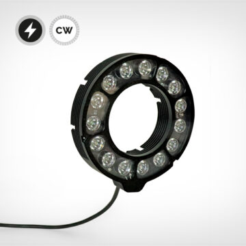
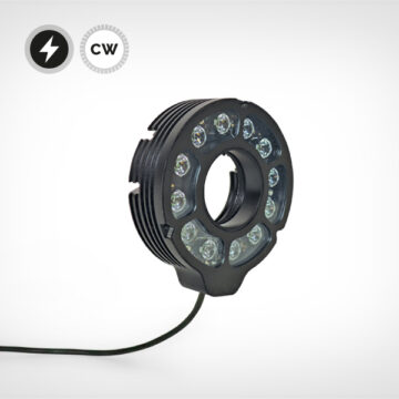
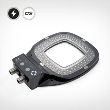
RING LIGHTS: Ring lights surround the camera’s optical axis, providing illumination from multiple directions around the inspection area. This arrangement can provide convenient, relatively uniform illumination for flat components and codes positioned within the light’s working area.
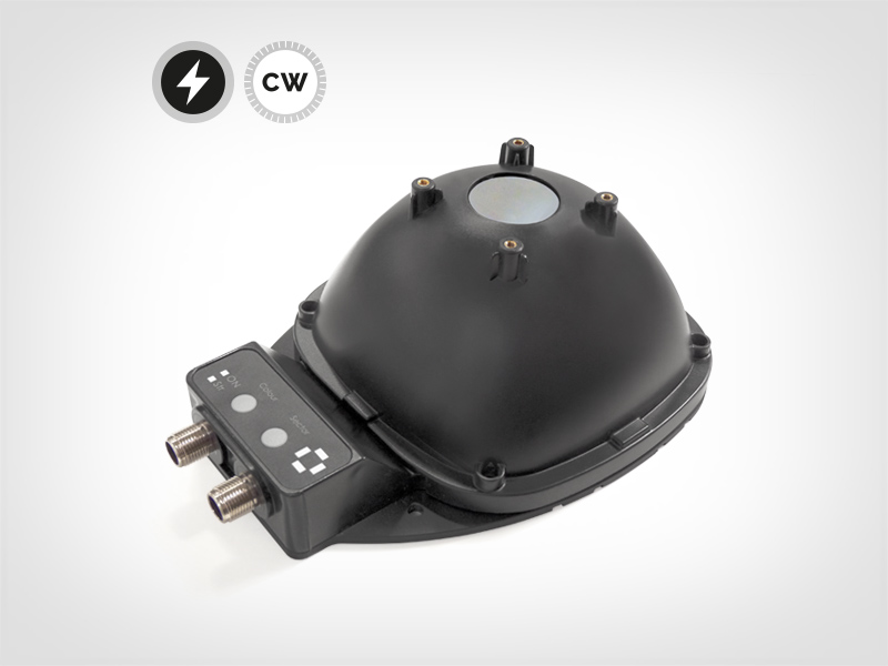
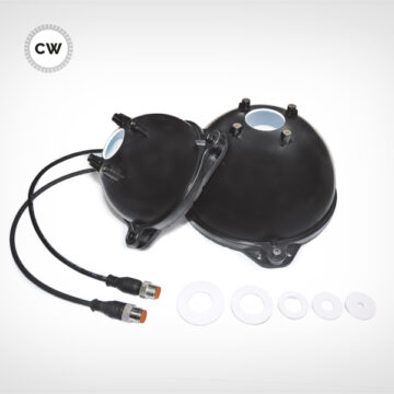
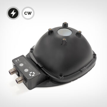
DIFFUSE/DOME LIGHTING: Dome lights reduce reflection, shade and shadow which may be caused by ambient lighting; this brings greater control to your machine vision solution. By reducing the visibility of unwanted reflections, diffuse illumination can make laser-marked codes easier to distinguish from the surrounding material.

| SURFACE | POTENTIAL CHALLENGE | LIGHTING CONSIDERATION |
|---|---|---|
| Polished Metal | Strong reflections/glare | Diffuse illumination, careful positioning |
| Brushed Metal | Directional reflections | Consider lighting angle relative the surface |
| Dark Plastic | Low contrast | Adjust wavelength and intensity |
| Light/Bright Surfaces | Insufficient mark contrast | Controlled illumination and exposure |
| Curved Surfaces | Uneven illumination | Larger/diffuse light source |
Putting the Lighting and Vision System Together.
A successful laser-marked code inspection system relies on more than the choice of light source.
The complete machine vision setup brings together several components:
Lighting -> Part -> Lens -> Camera -> Image Processing -> Code Reading
Is it flat or curved, matte or shiny, coloured or metallic, transparent or opaque? Surface finish determines whether you need diffuse, directional or backlighting.
Each element contributes to the final inspection result. Lighting determines how the code and surrounding surface are illuminated. This information is captured by the lens and camera, while exposure and image processing influence how clearly the code is represented in the resulting image. The code reading software uses this image to locate and decode the 2D symbol.

Summary
Reliable inspection of 2D laser-marked codes depends on capturing an image that clearly represents the code and its surrounding surface. Material reflections, surface finish, component geometry and marking characteristics can influence image quality, making lighting selection an important part of machine vision system design.
The key is to select lighting around the part, the mark and the camera as a complete system. A carefully configured setup can help improve image consistency and support reliable 2D code reading in demanding production environments.
Recommended products
-

Modular M-HPRING
- Versatile 76 mm ring light
- CW and Strobe OverDrive
- Angle Changer compatible
-

Modular M-TRING
- Powerful 37 mm ring light
- Direct attachment to C-mount lenses
- Angle Changer compatible
-

Small SDOME II
- Simple, lightweight dome light
- Current control integrated
- 80mm and 130mm IntØ
-

MR-Dome
- Powerful dome light
- Overdrive, sectors, bicolour
- 80mm and 130mm IntØ
-

Modular Ringlight
- Powerful, modular ring light
- OverDrive, sectors, bicolour
- Dome + Low Angle accessories